Chapter 4 Processor fundamentals
4.1 Central processing unit architecture
Von Neumann Architecture
- Von Neumann realized data and programs are indistinguishable & can therefore use the same memory
- Von Neumann architecture uses a single processor
- It follows a linear sequence of fetch–decode–execute operations for the set of instructions i.e. the program
- In order to do this, the processor has to use registers
The Processor
Arithmetic and logic unit (ALU): part of processor that performs arithmetic calculations & logical decisions
- Arithmetic operations: add, subtract, multiply etc.
- Logical operations: comparing binary patterns and making decisions
Control unit: part of processor that fetches instructions from memory, decodes them & synchronizes operations before sending signals to other parts of the computer.
System clock: timing device connected to the processor that synchronizes when fetch-execute cycle runs
Registers
an extremely fast piece of on-chip memory, usually 32 or 64 bits in size for temporary storage
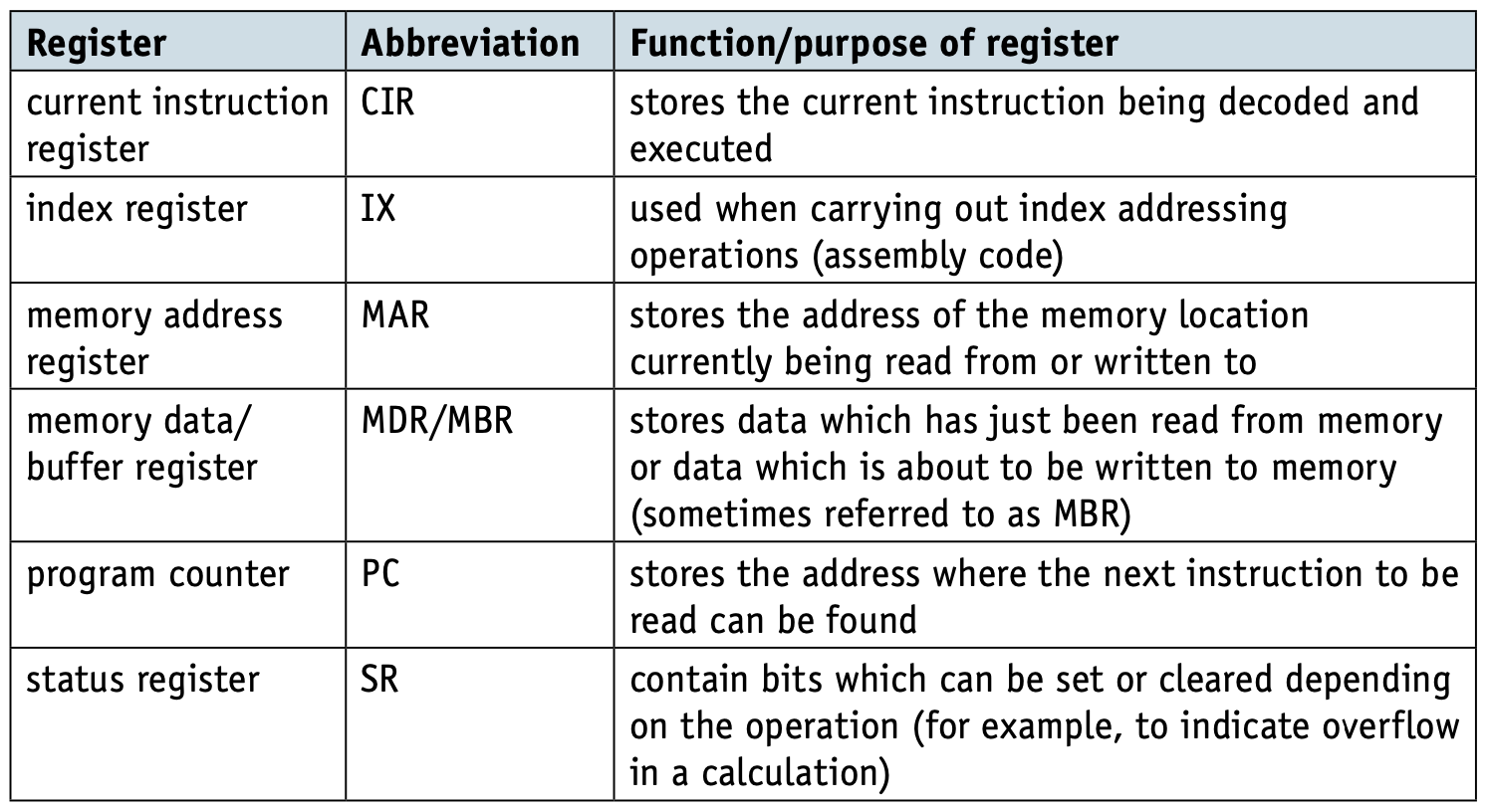
- General-purpose register: One or more registers in the CPU that temporarily store data
- Accumulator: single general-purpose register inside ALU. It is a single general-purpose register where all values held when processed by arithmetic & logical operations
btw, flags of Status Register: Carry(C), Negative(N), Overflow(V), Zero(Z)
System Buses
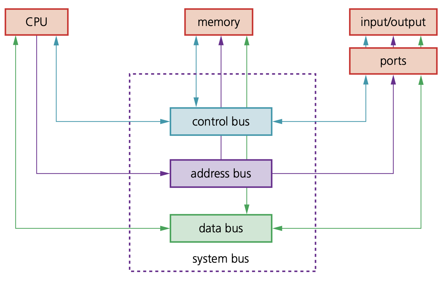
Address bus - carries addresses throughout the computer system. Between the CPU and memory the address bus is unidirectional, this prevents addresses being carried back to the CPU, which would be undesirable
Data bus - carry data and instructions between system components
Control bus - send control signals from control unit to ensure access/use of data & address buses by components of system does not lead to conflict
Performance of computer system
- increase bus width (bus width: determines maximum possible memory capacity of the system. Wider bus width means more bits can be transferred simultaneously)
- increase clock speed (clock speed: the number of cycles that are performed by the CPU per second. Faster clock speed means processes of fetch, decode and execute occur faster however faster clock speed causes processor to heat up)
- CPU with more cores
- increase cache memories (Cache uses SRAM whereas most computers use DRAM for main memory. Therefore, cache memories will have faster access times)
Fetch-execute cycle
Register Transfer Notation (RTN) of fetch-excute cycle
- MAR ← [PC] //contents of PC copied into MAR
- PC ← [PC] + 1 //PC is incremented by 1
- MDR ← [[MAR]] //data stored at address shown in MAR is copied into MDR
- CIR ← [MDR] //contents of MDR copied into CIR
- Decode
- Execute
- Return to start
// Direct address: load copy into MAR & retrieve data // Indirect address: add address to IR, copy result to MAR
Interupts
e.g.
software: software failure hardware: hardware error, I/O interrupt (printer no ink)
- Before each cycle, the interrupt register is checked.
- Depending on the priority of the interrupt, the running process is saved and the control of the processor is passed to the interrupt handler (ISR)
Sequence
- Current fetch-execute cycle completed
- Contents of all registers, especially PC, stored away
- Source of interrupt identified
- If low priority: then disabled
- If high priority: PC loaded with address of relevant ISR o ISR executed
- All registers except for PC are restored to original
- Interrupts re-enabled
- PC is then restored
- Return to start of cycle
4.2 Assembly language
Processor’s Instruction Set
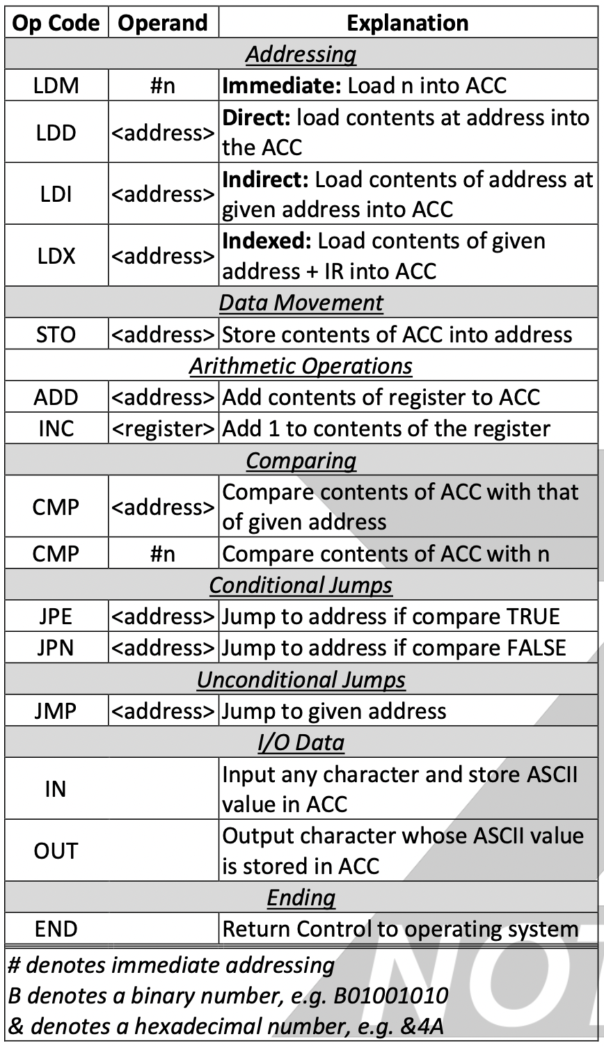
addressing
direct (absolute) addressing- the contents of the memory location in the operand are used
indirect addressing - the contents of the contents of the memory location in the operand are used
indexed addressing - the contents of the memory location found by adding the contents of the index register (IR) to the address of the memory location in the operand are used
immediate addressing - the value of the operand only is used
relative addressing - the memory address used is the current memory address added to the operand
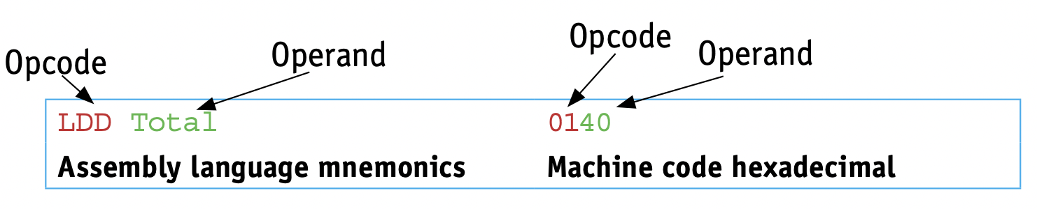
Symbolic addressing - only used in assembly language programming. A label is used instead of a value e.g. memory location with address labelled MyStore contained the value 20, LDD MyStore would store 20 in accumulator
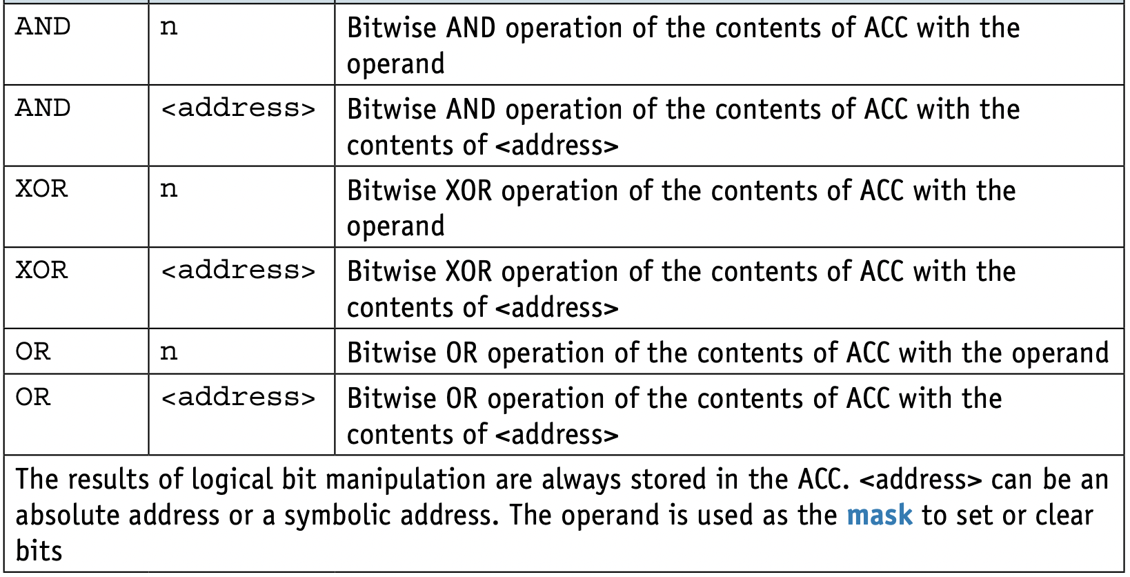
4.3 Bit manipulation
Binary shifts
moving the bits stored in a register a given number of places within the register
- Logical shift – bits shifted out of the register are replaced with zeros e.g. an 8-bit register containing the binary value 10101111 shifted left logically three places would become 01111000
- Arithmetic shift - the sign of the number is preserved e.g. an 8-bit register containing the binary value 10101111 shifted right arithmetically three places would become 11110101
- Cyclic shift - no bits are lost during a shift. Bits shifted out of one end of the register are introduced at the other end of the register e.g. an 8-bit register containing the binary value 10101111 shifted left cyclically three places would become 01111101
- Left shift – bits are shifted to the left; gives the direction of shift for logical, arithmetic and cyclic shifts
- Right shift – bits are shifted to the right; gives the direction of shift for logical, arithmetic and cyclic shifts

Bit manipulation used in monitoring and control